Viewing Photon's raw image data would depict a monochrome image with a stark checkerboard pattern, so it's Photon Transfer's job to convert the raw image data to an acceptable color image:
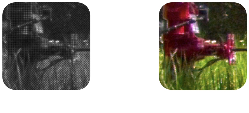
Note the checkerboard pattern visible in the RAW image, caused by the Bayer pattern of the image sensor
Image Pipeline Overview
The image pipeline contains the following stages: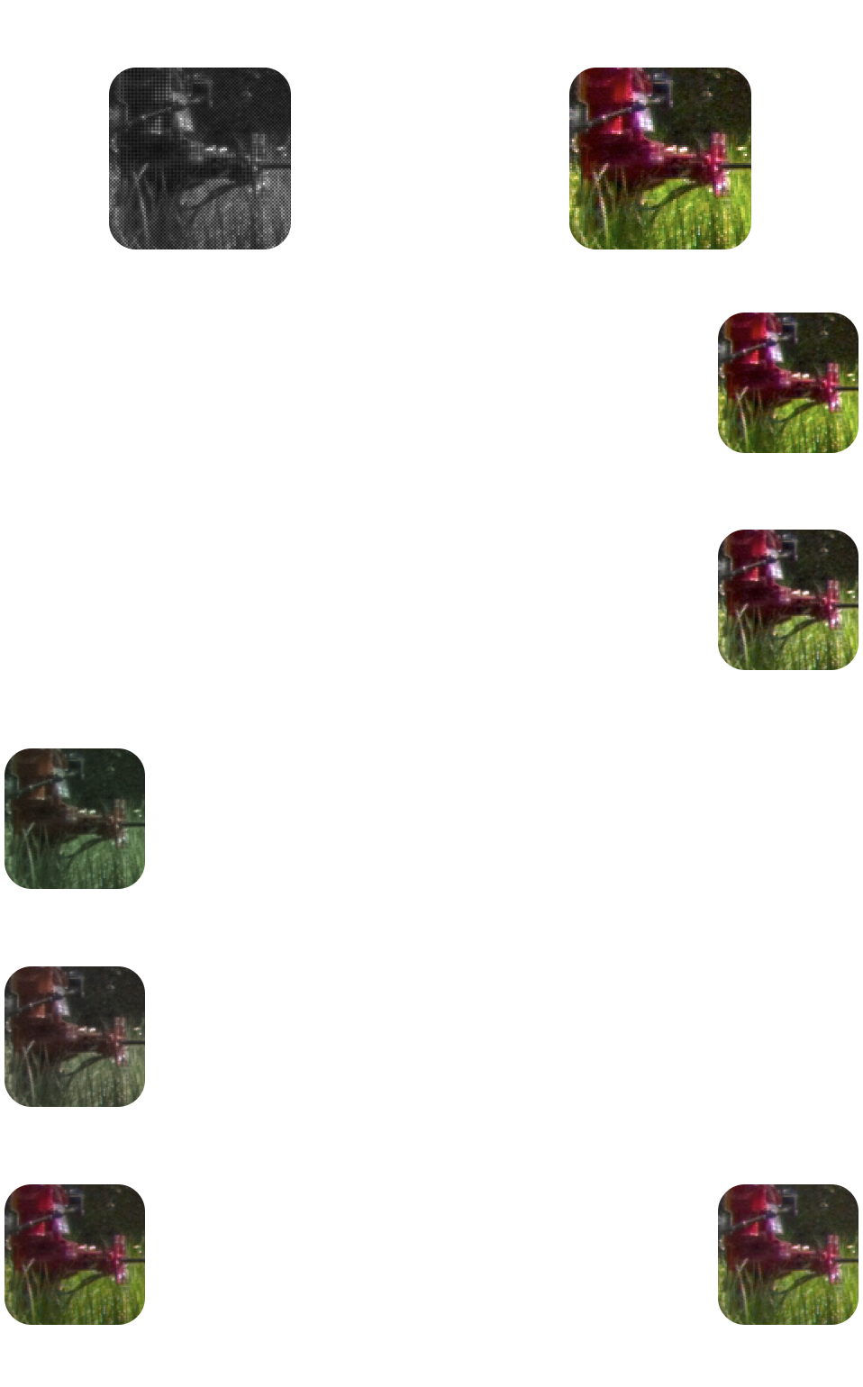
Left column: the automatic stages that aren't configurable
Right column: the user-controlled "artistic" stages
Photon Transfer's image pipeline is implemented in C++ and Metal shaders so that the heavy lifting can be performed efficiently on the GPU. All of the source is available on GitHub; you can follow along with this blog post by looking at ImagePipeline.mm.
Illuminant Estimation
Since the image pipeline doesn't know the light source that's illuminating a scene, it's the job of the first stage to estimate it so that later stages (specifically, highlight reconstruction and white balancing) can use this information.There are many techniques to perform illuminant estimation and it's an active topic of academic research. Photon Transfer uses Fast Fourier Color Constancy (FFCC) for illuminant estimation, which is fast (~2.6ms per image) and delivers good-quality output.
Highlight Reconstruction
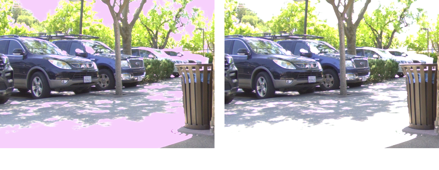
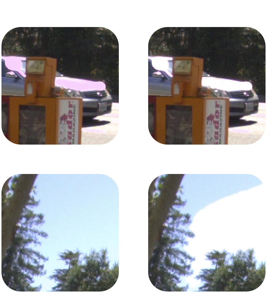
When capturing a photo there are typically regions that are over-exposed — highlights — which causes one or more of the RGB channels to clip to the maximum pixel value. (Photon uses 12-bit pixels, so highlights are clipped to 212-1 = 4095.)Without explicit processing for these clipped pixels, chromatic distortions occur in the final output image. The green channel is most prone to clipping, so the distortions typically appear as magenta regions:
Debayer
The Debayer stage is responsible for converting the single-channel RAW image to a 3-channel RGB image:Debayering is an active topic of academic research, and Photon Transfer uses Linear Minimum Mean Square-Error Estimation (LMMSE) to perform debayering.
White Balance
White balancing adjusts the colors of the image so that neutral colors actually appear neural, effectively removing the green tint of the debayered image: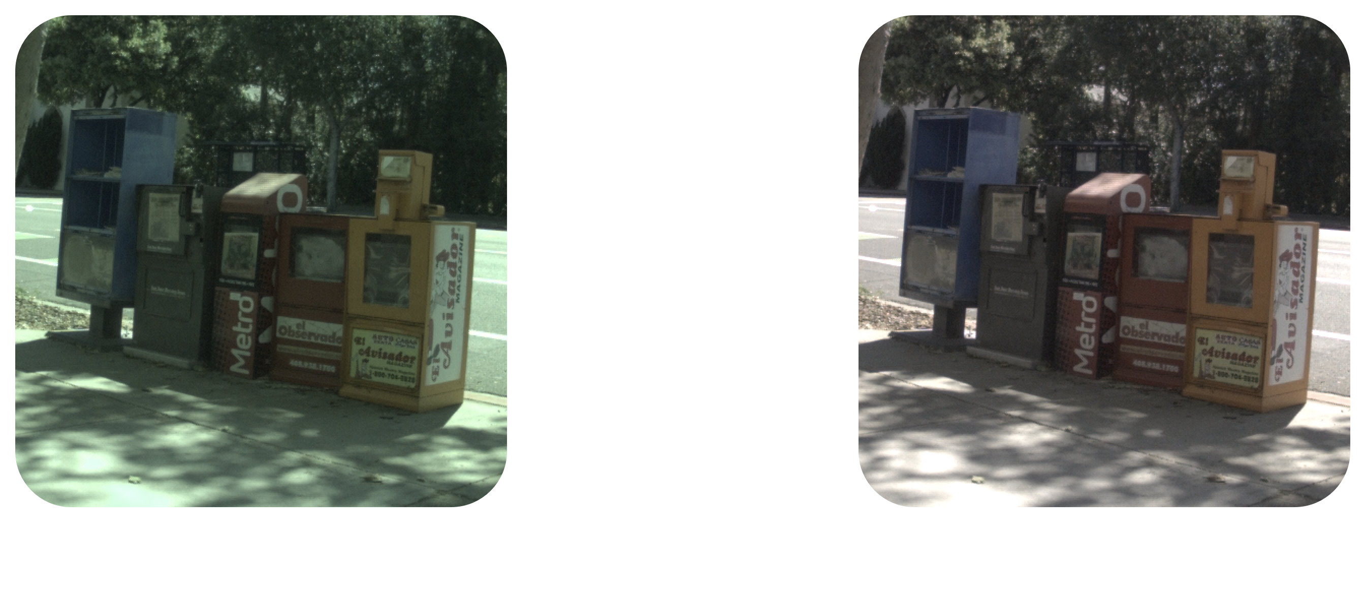
Note how the sidewalk is transformed from green-tinted to gray.
Color Correction
The final stage of the "automatic" image pipeline is color correction: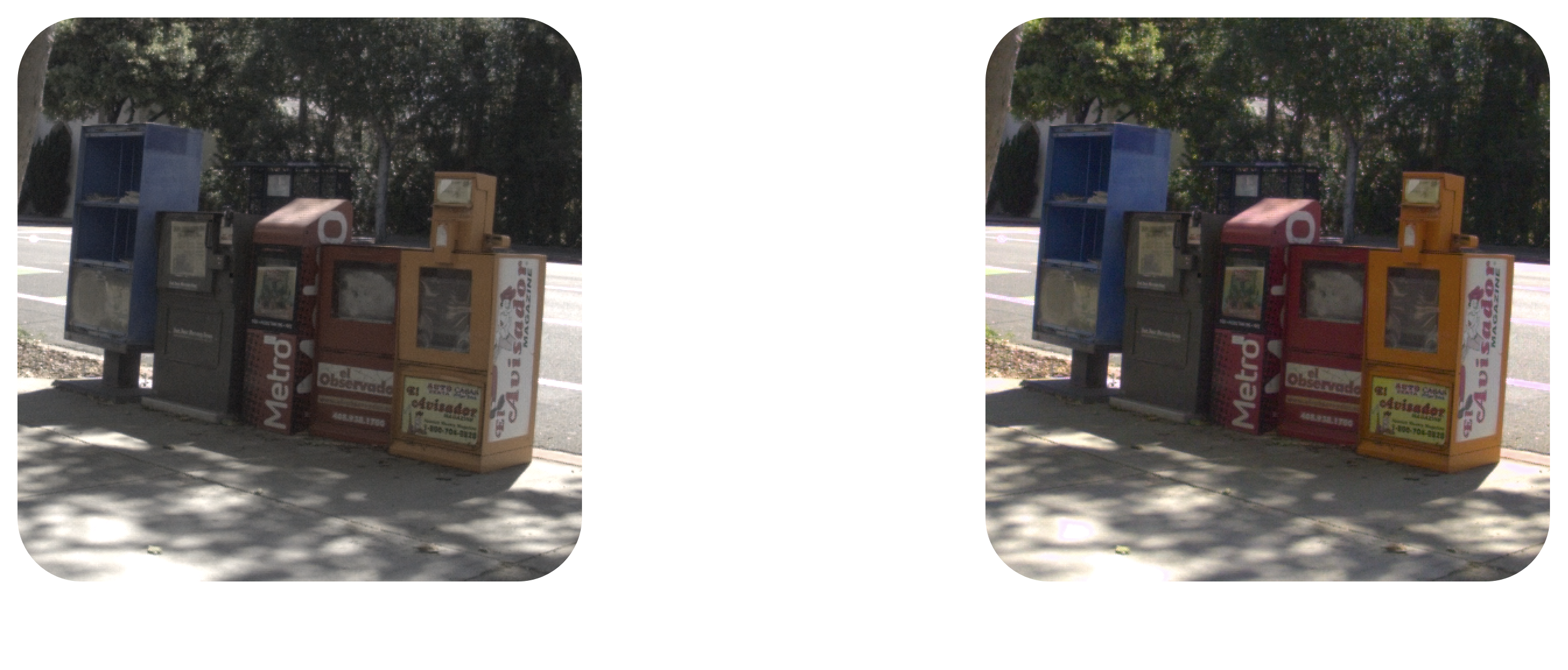
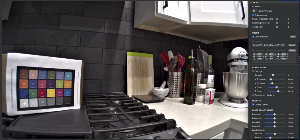
The circles on the color-calibration chart are placed manually in order the compute the color-correction matrix shown in the panel on the right.
Ax=b, we'll set x to the image sensor's perceived color of the 24 calibration squares, and we'll set b to the ground truth color of the 24 calibration squares. In other words, x is what we have, b is what we want, and A is the transformation that'll get us there: A. We'll rearrange the equation into the standard form Ax=b: Ax=b with respect to what we want to solve for (ie we want AT which is in the position of x in the standard equation), we can do a least-squares regression, transpose the result, and we have A! White Balance Stability
An important property of the CCM is that it doesn't disturb the white balance of the image that was established in the previous stage. In other words, a neutral color multiplied by the CCM must remain a neutral color. To ensure that the CCM has this property, we'll perform one last step: we'll divide each row of the CCM by the sum of its three components. This ensures that each row of the CCM sums to 1, and therefore a neutral color multiplied by the CCM will remain a neutral color.
User-Controlled Stages
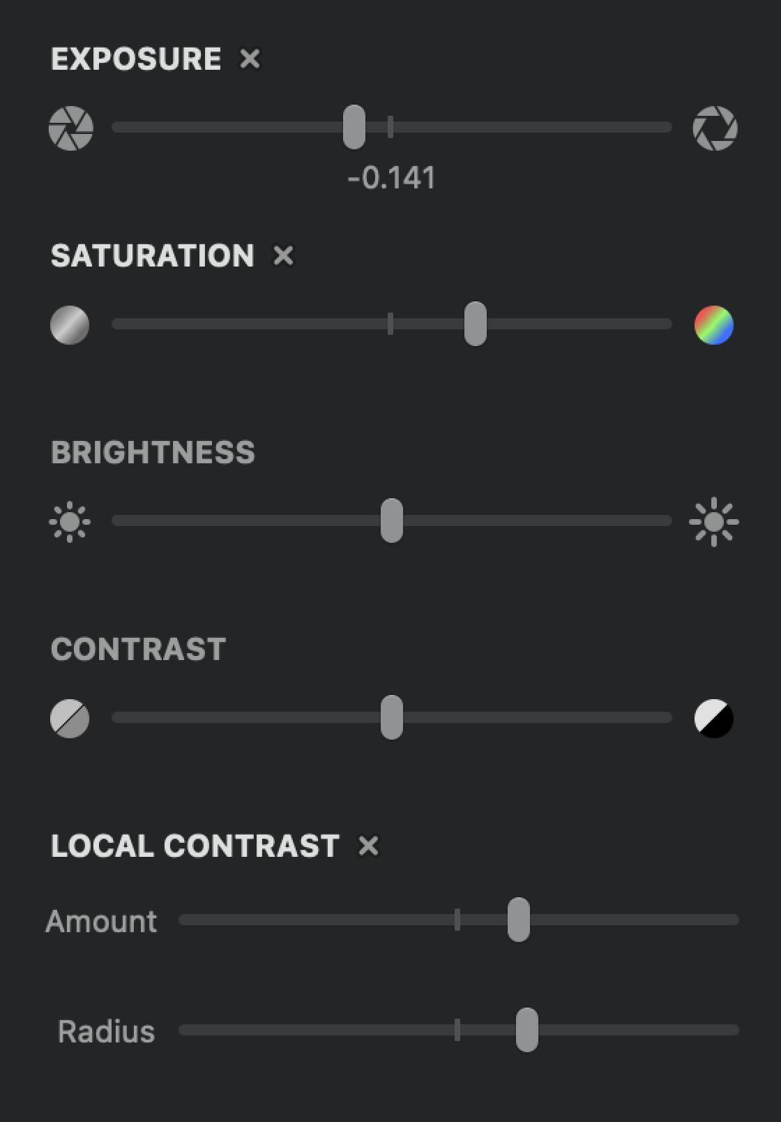
The remaining stages of the image pipeline allow for manual image adjustment to suit the user's preferences: